Is it worth to change to a nano cam? Depends, if every gramm counts definitly, RunCam Nano has nearly 1/4 of the weight.
RunCam Racer Nano 2: 4g
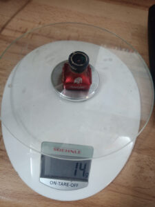
RunCam Eagle2: 14g
Is it worth to change to a nano cam? Depends, if every gramm counts definitly, RunCam Nano has nearly 1/4 of the weight.
RunCam Racer Nano 2: 4g
RunCam Eagle2: 14g
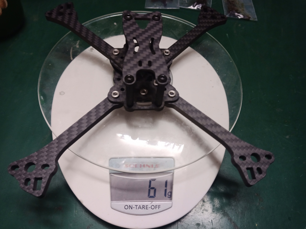
Got my new frame FIVE33 SWITCHBACK from https://flyfive33.eu/
Final goal is to get a new copter <= 300g
be aware this frame supports only Nano Cams and has stand alone only 61g
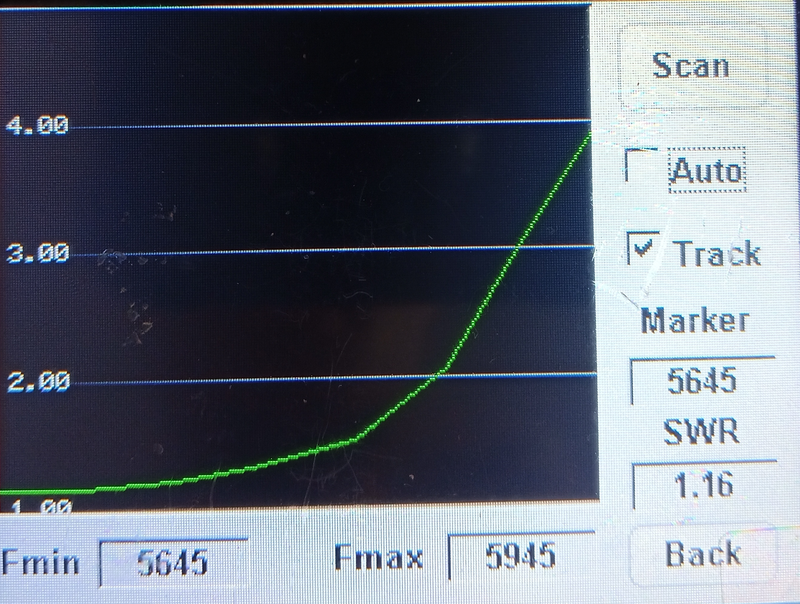
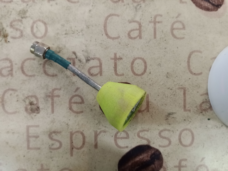
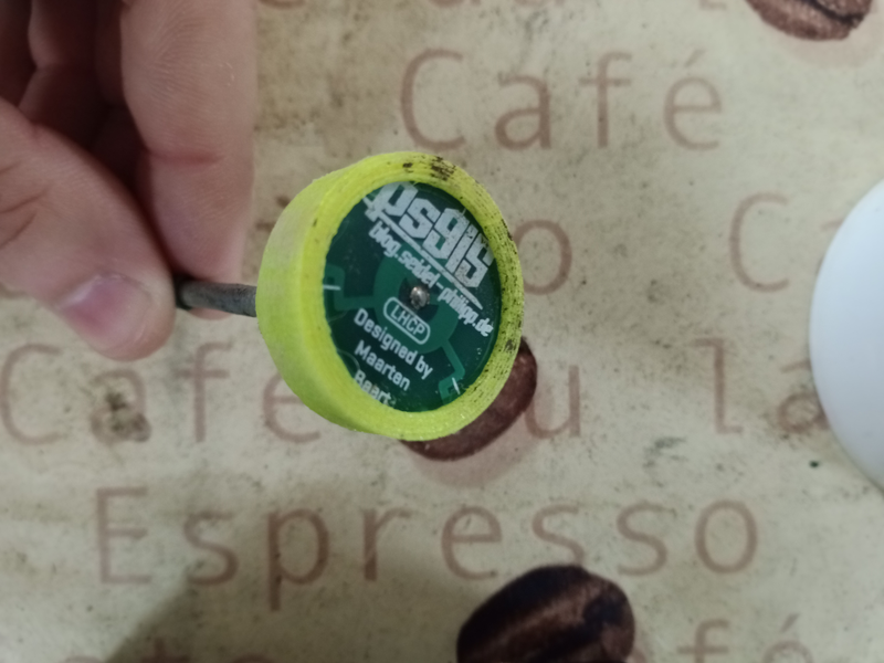
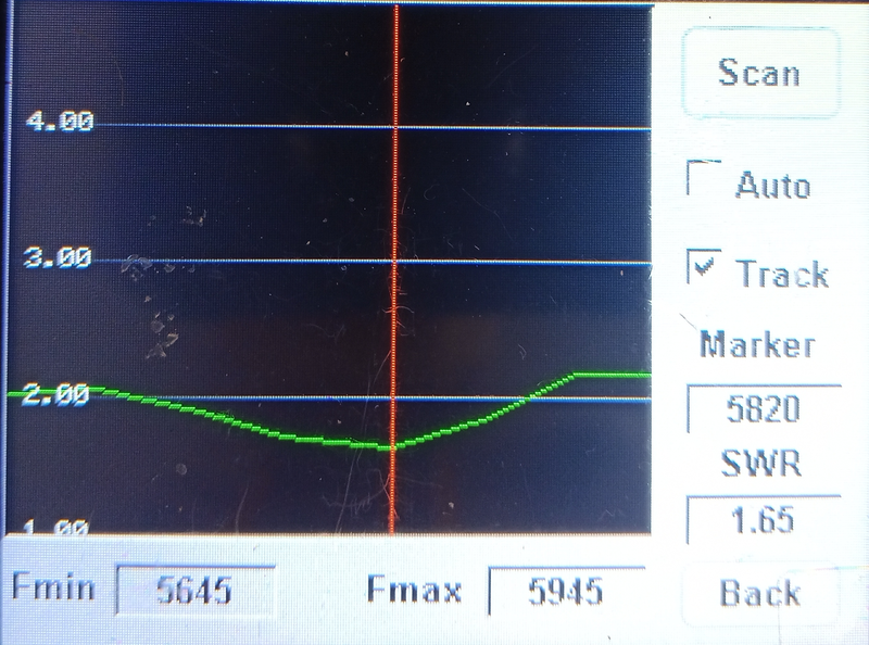
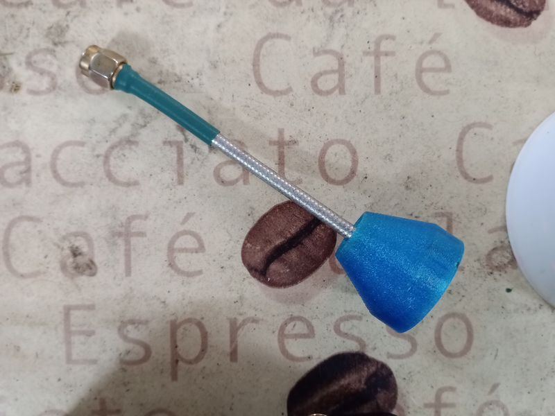
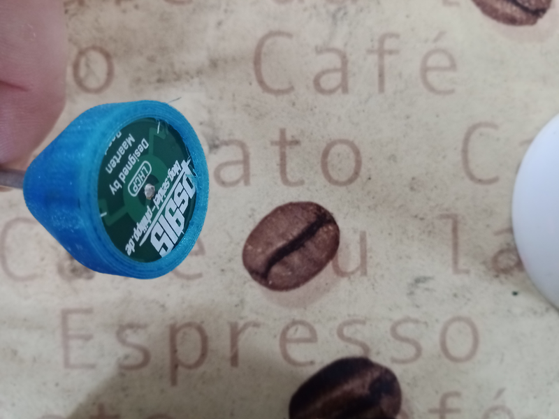
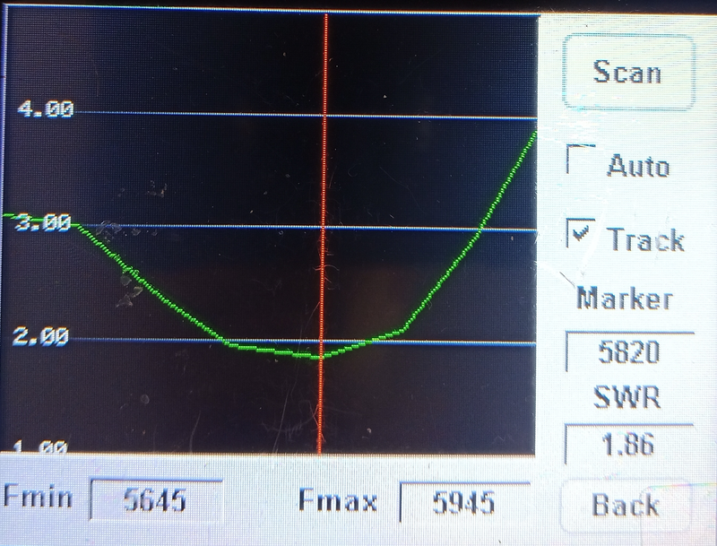
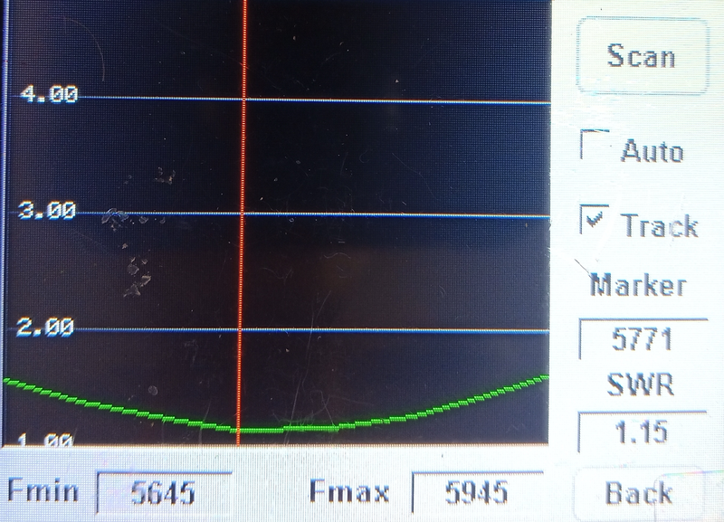
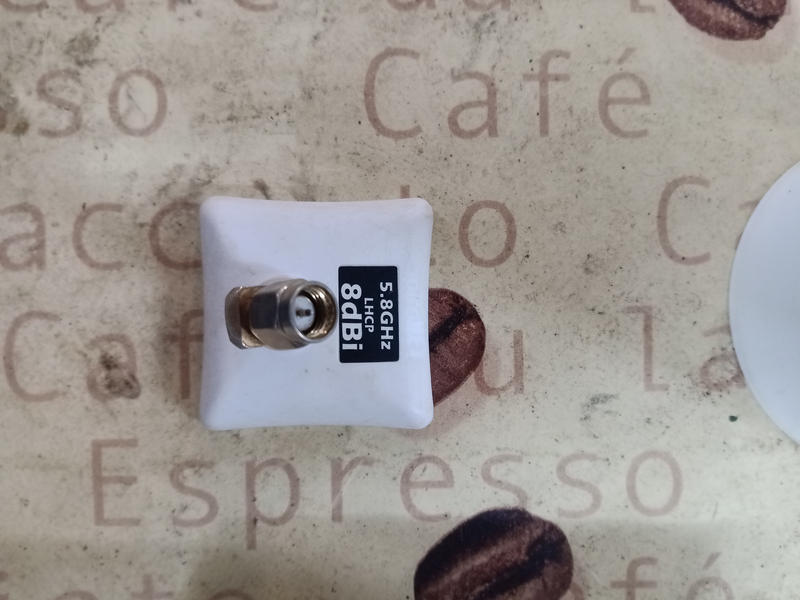
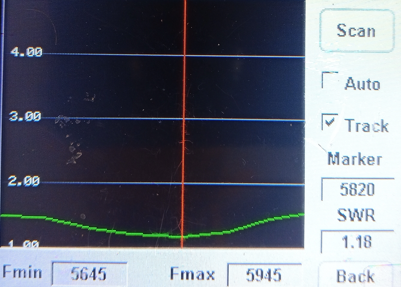
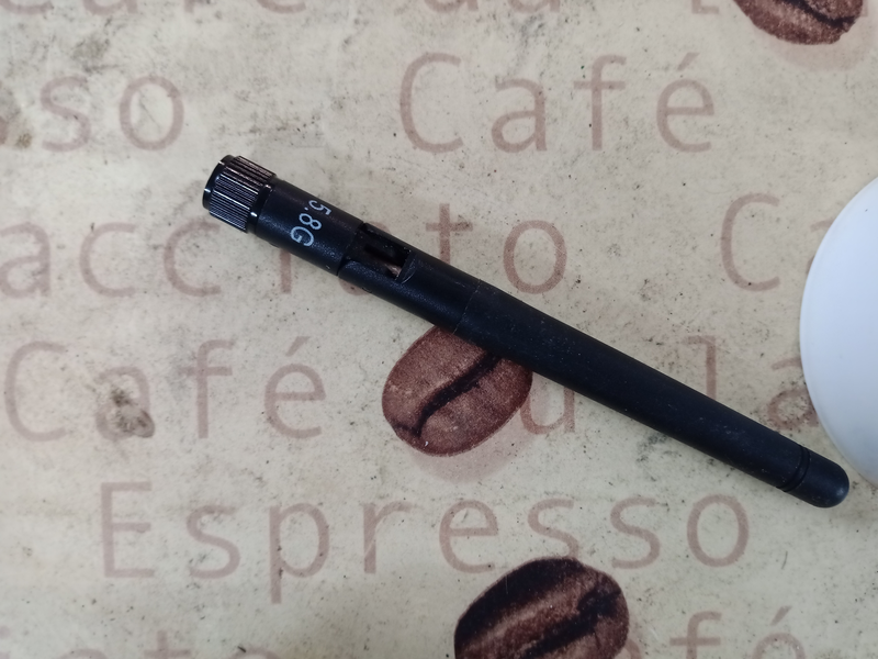
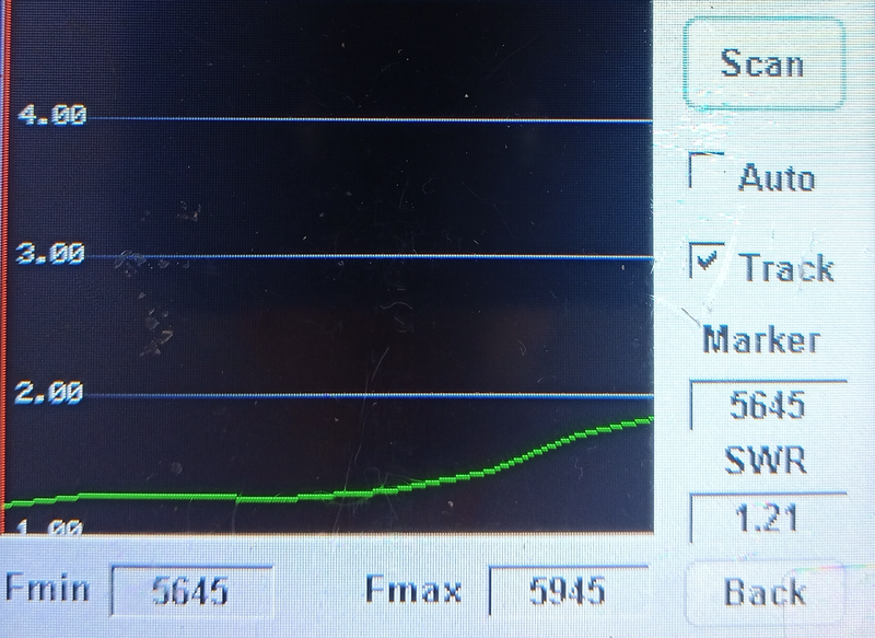
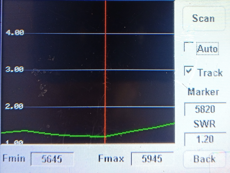
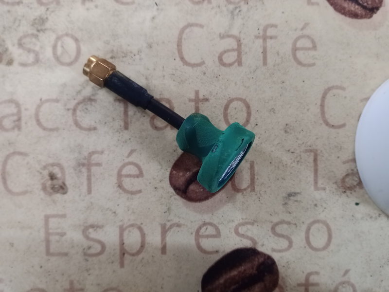
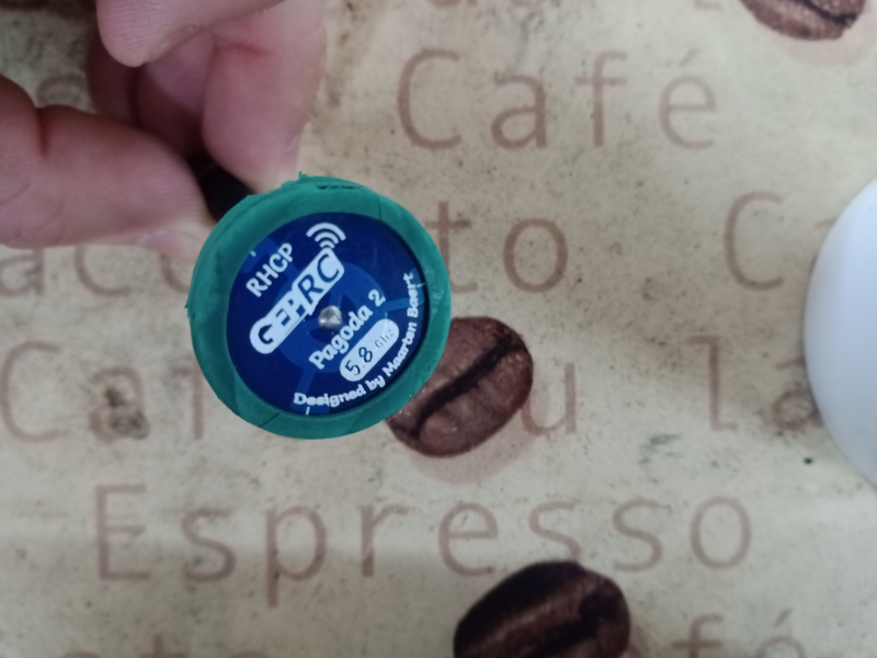
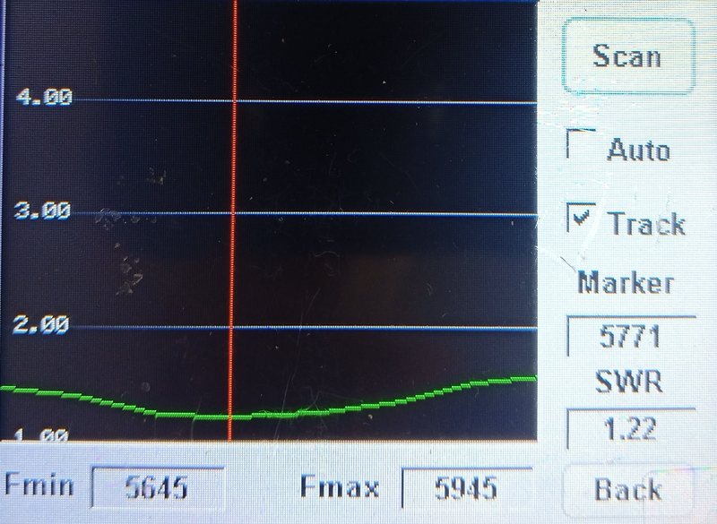
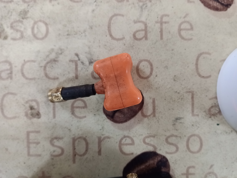
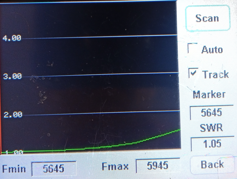
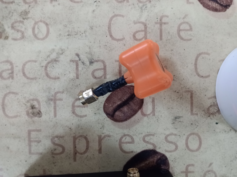
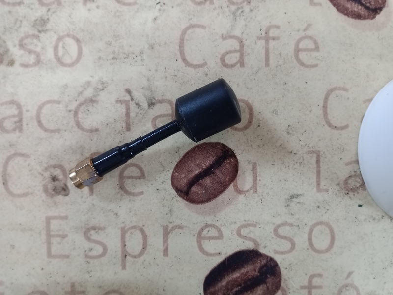
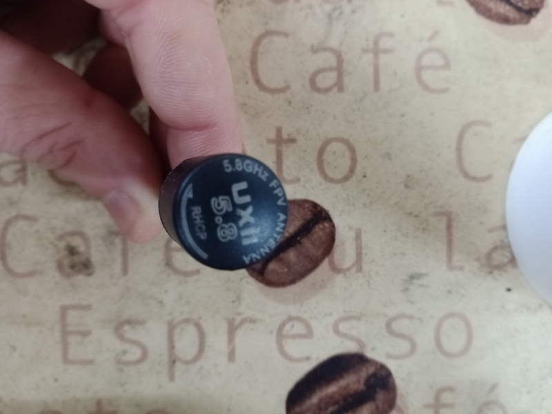
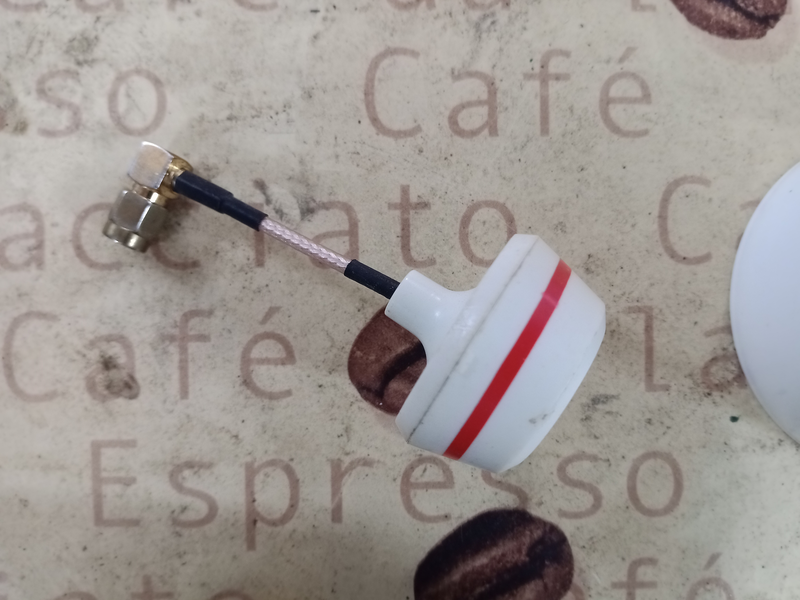
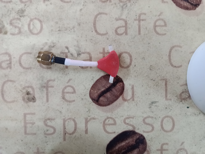
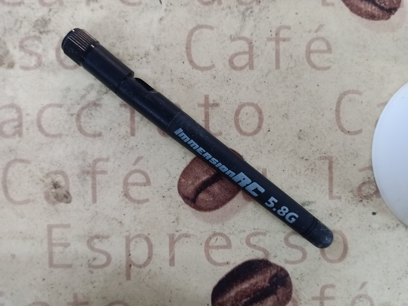
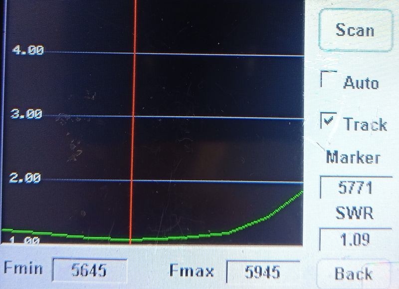
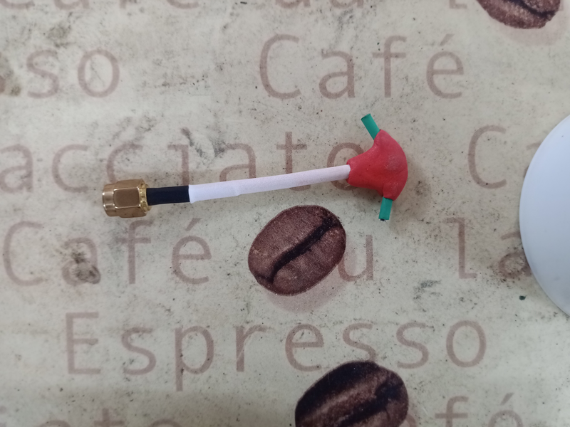
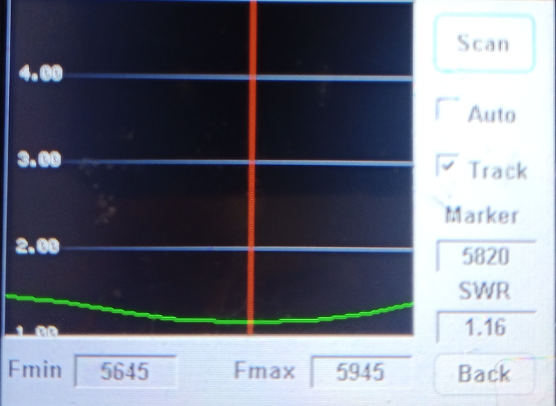
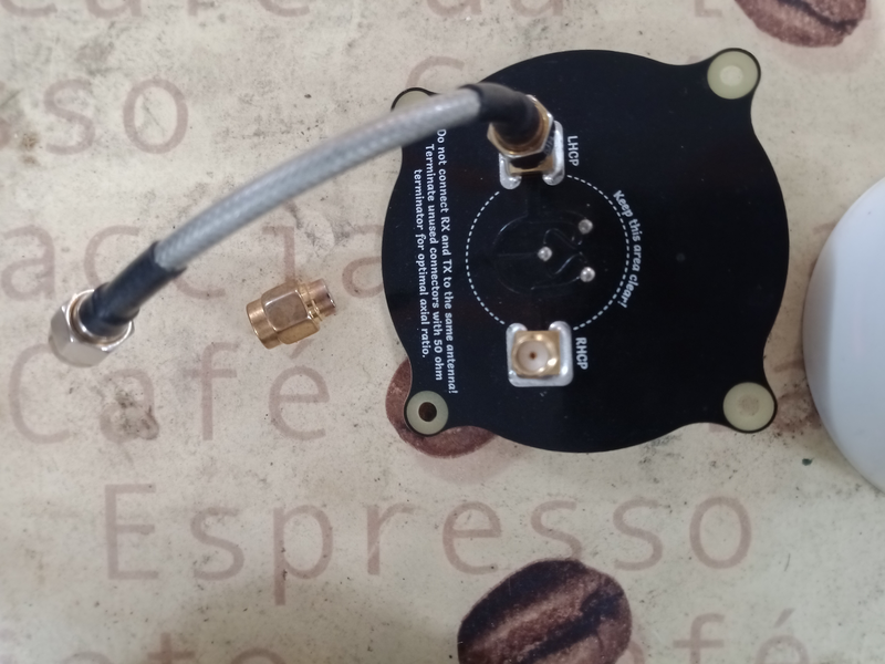
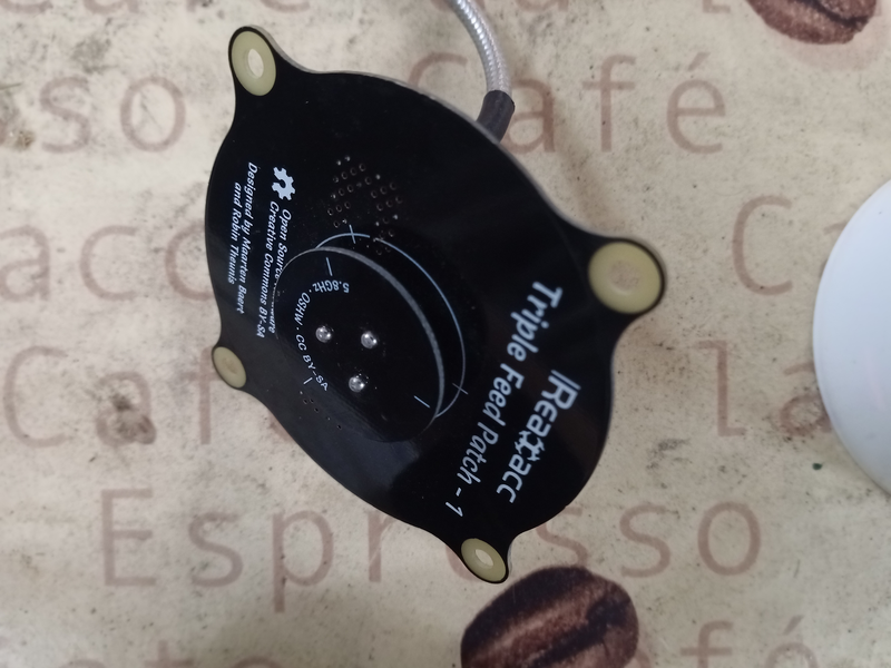
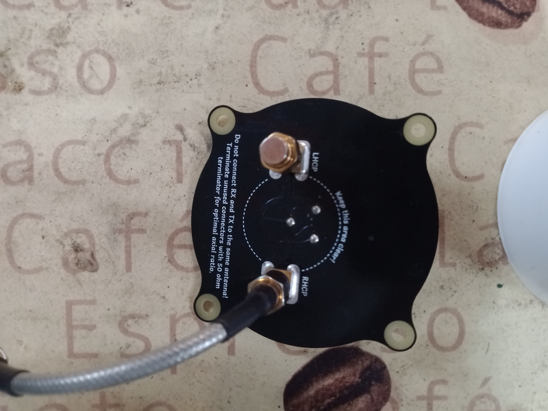
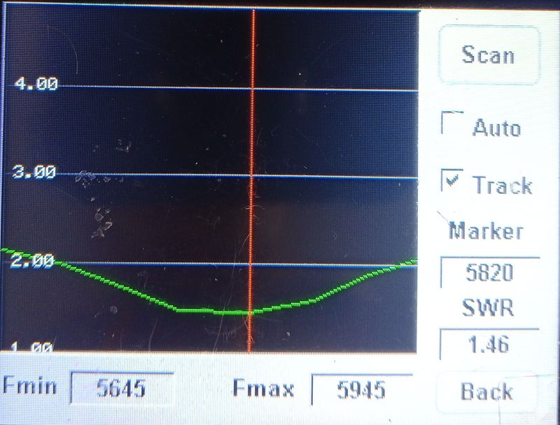
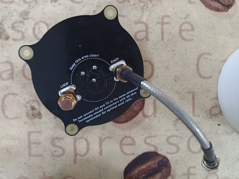
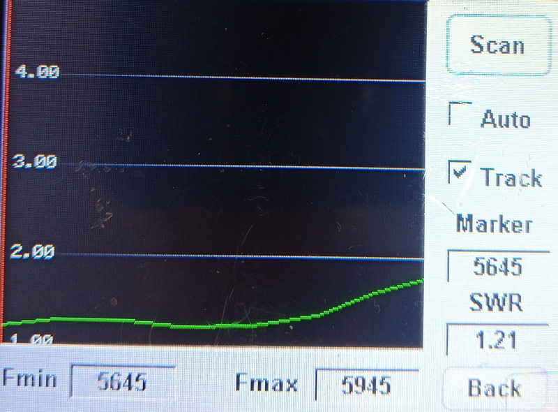
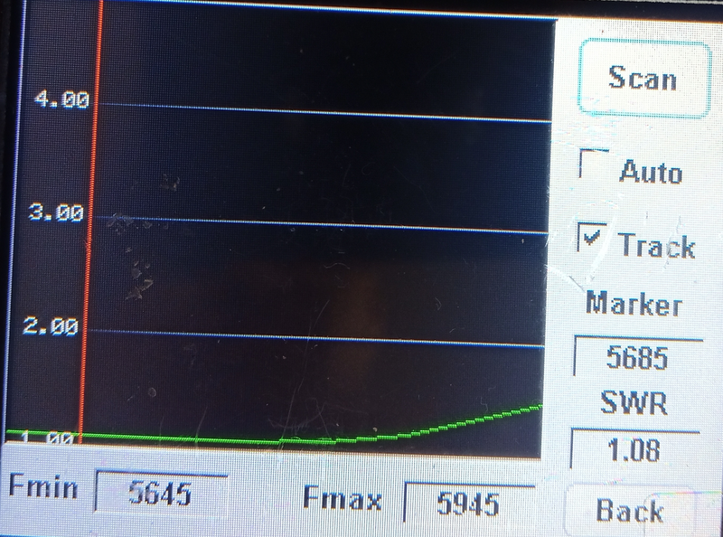
Got finally now the 5ghz swr meter:
Cause i didn’t found measures and comparison tables in the internet i tested all my antennas i found. Please be aware this measurement are not really reliable, they should deliver you a rough overview. If you got different results please post your measurements for discussion.


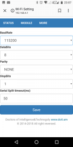
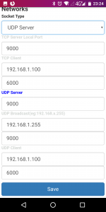
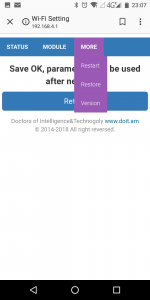
This steps requires some patient, wlan always makes some troubles. Took me nearly half an hour, since than it worked more or less stable, sometimes i have to double connect. Please test it also without a android if you have troubles. Androids hates it if wlan have no internet connection, sometimes it doesn’t really add routes for the local network -> Means it show connected but your mobile phone sends nothing to the access point. Because android want to keep the user into dark(or i would say stupid^^) you don’t have many debug options per default. Better try with Laptop if you had too much troubles, lets get started with the wiring setup:


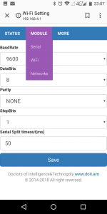


Took a look at frsky homepage and found new firmware version for the rxsr fport edition come out this year: 2019-01-09
Just download it copy it to the sdcard on the Taranis under Firmware, wire it like on this picture, go into the Menü -> 2/9 SDCARD/Firmware and choose right version -> select flash external device, wait for loading screen -> done
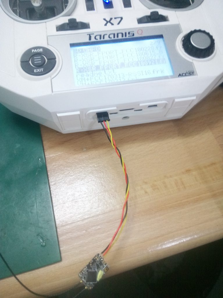
If you have a normal X9D Taranis take a look oscarlians blog. Be aware the power supply/red pin is not in middle, so you have to adjust the wiring.
After trying to forget the usb troubles i started with testing the final setup. Go into the OSD Menü (left stick: left, right stick up) and tried to change the Tramp transmitting frequency under features -> TR. Normally should be there depending on t he settings Band “Fatshark” instead there was “Boscam A”. It was kind strange but lets try it, after confirming new channel with set nothing happens! Normally you should get white noise in your FPV goggles because the channel should change.
Confirmed soldering to the right uart pin, must be the TX pin, because its a half duplex protocol. Also the right serial was set in betaflight to IRC Tramp -> Serial6. Also the cli option vtx_halfduplex was set to “ON” like its default.
Okay lets go deeper and measure the signal:
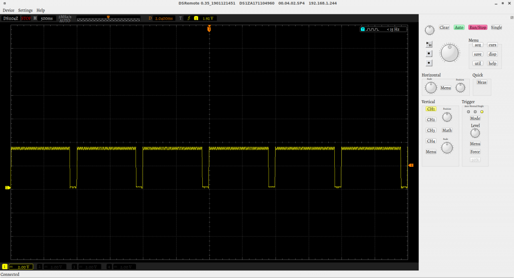
Lets try uart1 as reference, worked with first try:
Lets take a look to betaflight wiki: On OMNIBUS F4 V3 and later, serial RX is UART6, not UART1.
So conclusion is that Uart6 TX Pin is not mapped directly to the uart6 tx pin, i assume there must be some hardware inverter used to receive sbus signals which is blocking the signal.
Its still pita, without schematic we have to believe what we get and debugging is hell, hopefully we will get a open schematic flight controller with a F4 like the old CC3D. As workaround i use now Uart1 TX Pin, luckily i have one uart left.
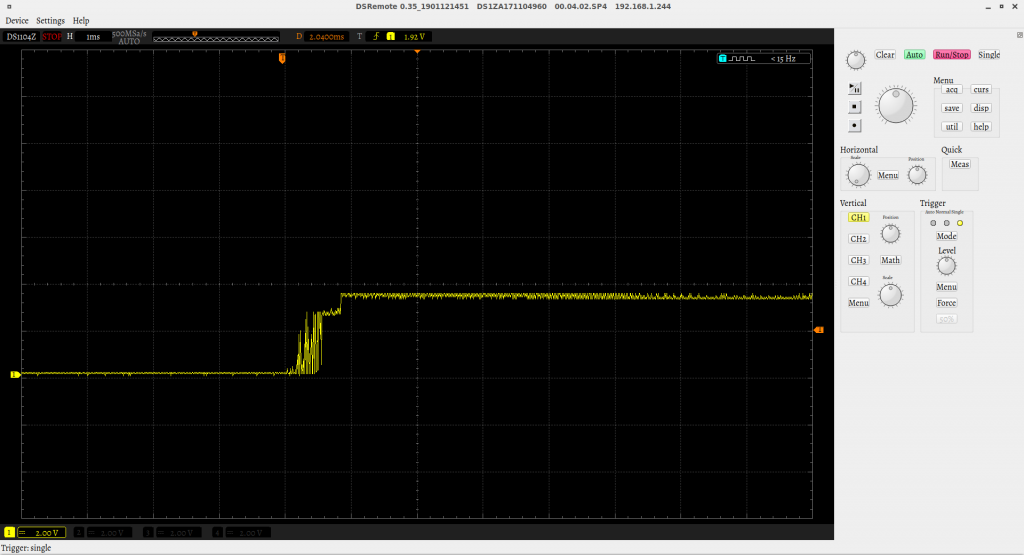
After changing flight controller because of USB i wanted to start the setup, so i connected copter via USB –> “NO SERIAL APPEARED”
I got really salty because that’s was the only reason why i changed the omnibus. But question was still why, took a look into the linux kernel log. (enter dmesg in console):
[316073.353128] usb 8-2.4.3: device not accepting address 56, error -71
[316073.537119] usb 8-2.4.3: new full-speed USB device number 57 using uhci_hcd
[316073.957079] usb 8-2.4.3: device not accepting address 57, error -71
[316073.958253] usb 8-2.4-port3: unable to enumerate USB device
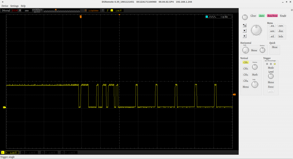
Found only waste to error Code -71. Nothing useful at all in the whole internet )=. If you have something for me please post it! Only after connecting several times serial appeared very rare, tried a standalone onmibus without anything else connected which was lying around:
[316781.674161] usb 8-2.4.3: new full-speed USB device number 58 using uhci_hcd
[316781.933188] usb 8-2.4.3: New USB device found, idVendor=0483, idProduct=5740
[316781.933191] usb 8-2.4.3: New USB device strings: Mfr=1, Product=2, SerialNumber=3
[316781.933193] usb 8-2.4.3: Product: OmnibusF4
[316781.933195] usb 8-2.4.3: Manufacturer: Betaflight
[316781.933197] usb 8-2.4.3: SerialNumber: 0x8000000
[316781.937288] cdc_acm 8-2.4.3:1.0: ttyACM1: USB ACM device
worked at first try, so i assumed they forget the pull up resistor on D+ for detecting the USB Device, what for example happened on the blue pill (stm32 based arduino board)
Because it worked one time i assumed its an electric issue, i measured everything, found 22 Ohm in Series at D+ and D-, strange thing was everything was the same with the working one. Strange i did not found the 1k5 pull up resistor, found out its internal on the stm32F4 (bluepill uses F3) => why the hell it does not work than? Had no idea left, so i put a lot of solderflux at the usb connector and heated with solder iron to the usb connector and the serial resistors. Connected again -> suddenly it worked out of the box. However betaflight was really slow, saw always loading screen, on laptop it work fast as it should -> found out 3d printer was using maybe nearly complete USB bandwidth.
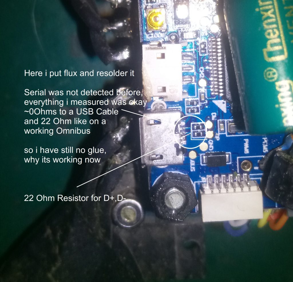
Lessons learned: Test flight controller and usb right before you built it in and don’t use other serials while one is occupied by the 3d printer.
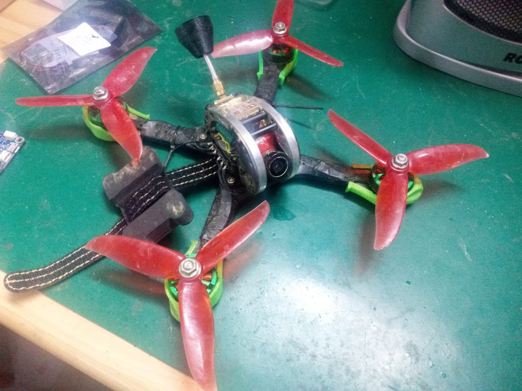
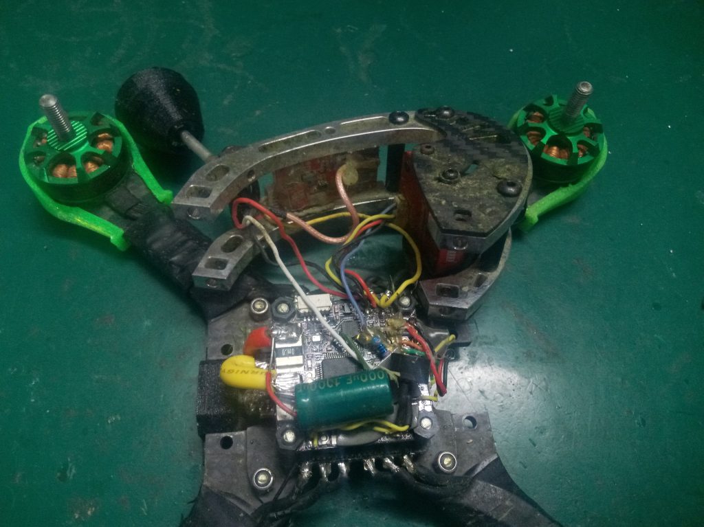
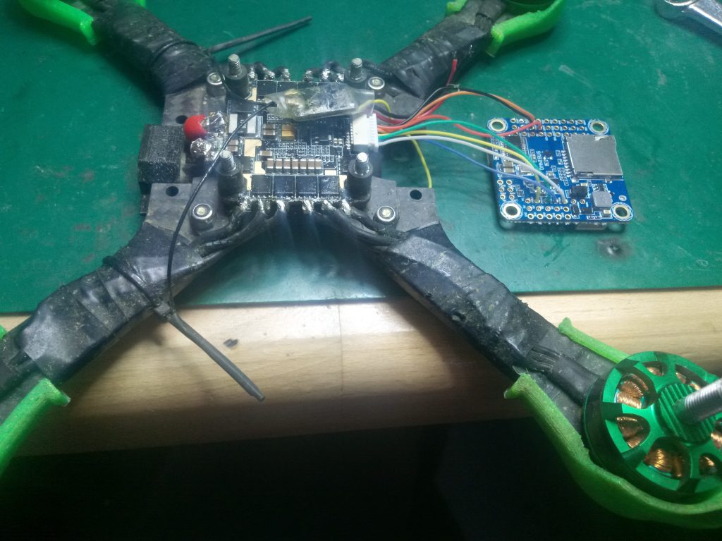
Copter Season is starting already (: so i had to repair and maintenance my old copters, unlucky i broke the usb port from my Obsession Quad, I replaced the Omnibus F4 V3 flight controller with the pro version(means no current sensor on board anymore, however i am able to get the current sensor data from the 4in1 ESC modul). See the detailed spec of the Obsession under Quadcopers.
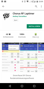
Next step is to get the software on the arduino. Get the latest source:
git clone https://github.com/voroshkov/Chorus-RF-Laptimer.git
So i started my Arduino IDE (i used version 1.8.5), open the Ino file in the Chorus-RF-Laptimer folder and click on compile and following error appeared ):
/tmp/arduino_build_387930/sketch/mainDetectionAlgorithm.h: In function ‘void runExperimentalLapDetectionAlgorithm()’:
/tmp/arduino_build_387930/sketch/mainDetectionAlgorithm.h:53:41: error: ‘getDeepFilteredRSSI’ was not declared in this scope
rssi2 = getDeepFilteredRSSI();
Took a short look into the source, but didn’t find the getDeepFilteredRSSI, maybe it was forgotten to check in. So i rolled backed to latest stable version:replica uhren
cd Chorus-RF-Laptime
git checkout -b 0.7.9
And finally it build through (: with git tag you can see all other tagged versions that exists
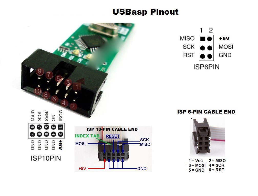
For programming Arduino’s i purchased a USBASP programmer. They are quite cheap and available for some dollars from china (e.g. banggood)
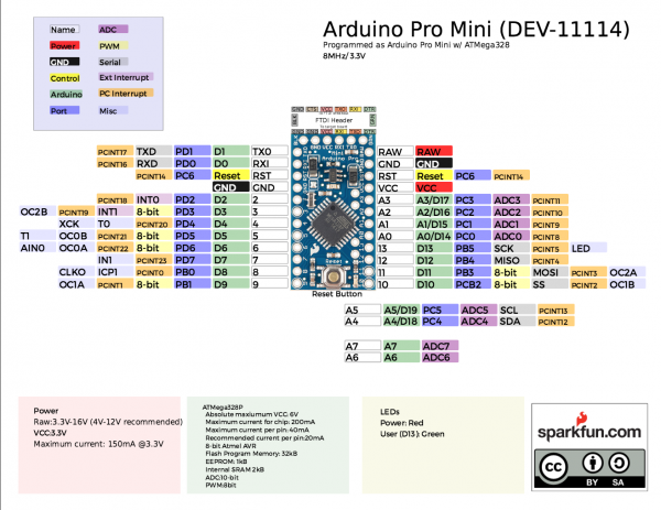
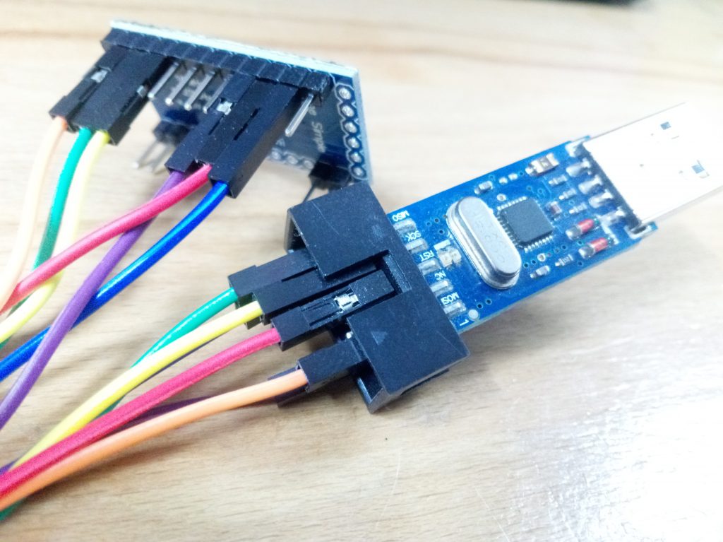
You have to connect folling PINs:
MISO<->MISO
SCK<->SCK
MOSI<->MOSI
RST<->RST
VCC<->5V
GND<->GND
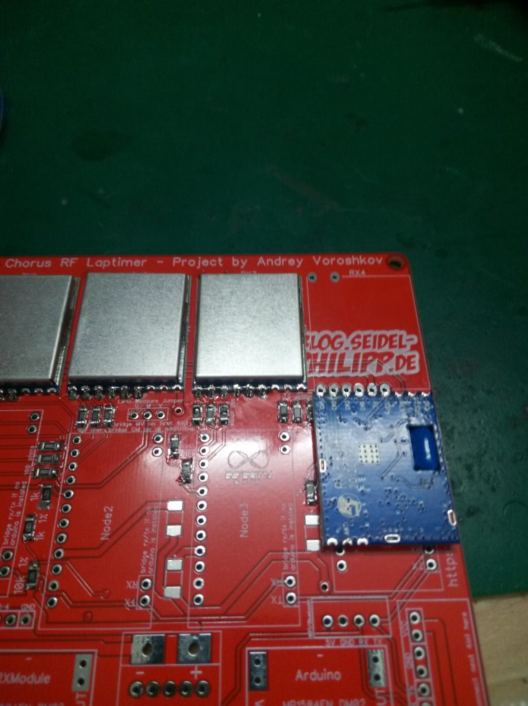
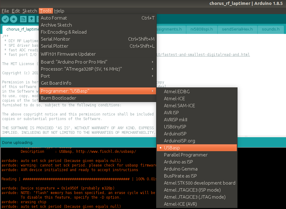
Connect programmer to your PC, select right Arduino in the IDE -> “Arduino Pro or ProMini with Processor ATmega328P (5V, 16Mhz)” and also the right Programmer “USBasp”. Finally program it via Sketch -> Upload using Programmer.
Now repeat this for the other three and done (=
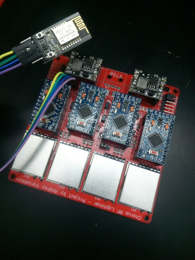
Got some time ago a 4in1 Laptimer pcb from bernd, see http://kwads.at/chorus-rf-laptimer-4in1 (schematic & layout is available under https://github.com/ps915/Chorus-RF-Laptimer-PCB)
Started ordering parts immediately, meanwhile all parts are arrived and I’m finally able to start soldering it together. Here is my order list (from banggood+aliexpress, be aware it could take 2-3 weeks to get all stuff):