Got some time ago a 4in1 Laptimer pcb from bernd, see http://kwads.at/chorus-rf-laptimer-4in1 (schematic & layout is available under https://github.com/ps915/Chorus-RF-Laptimer-PCB)
Started ordering parts immediately, meanwhile all parts are arrived and I’m finally able to start soldering it together. Here is my order list (from banggood+aliexpress, be aware it could take 2-3 weeks to get all stuff):
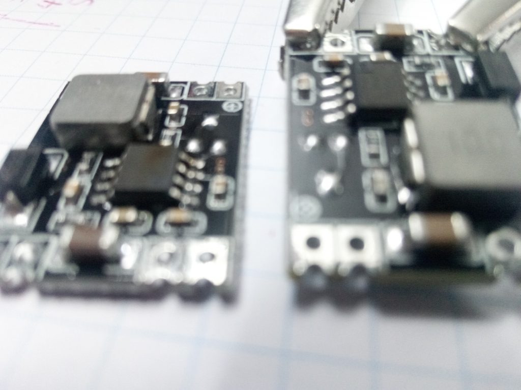
- One set of 5 pieces DC/DC stepdown converter
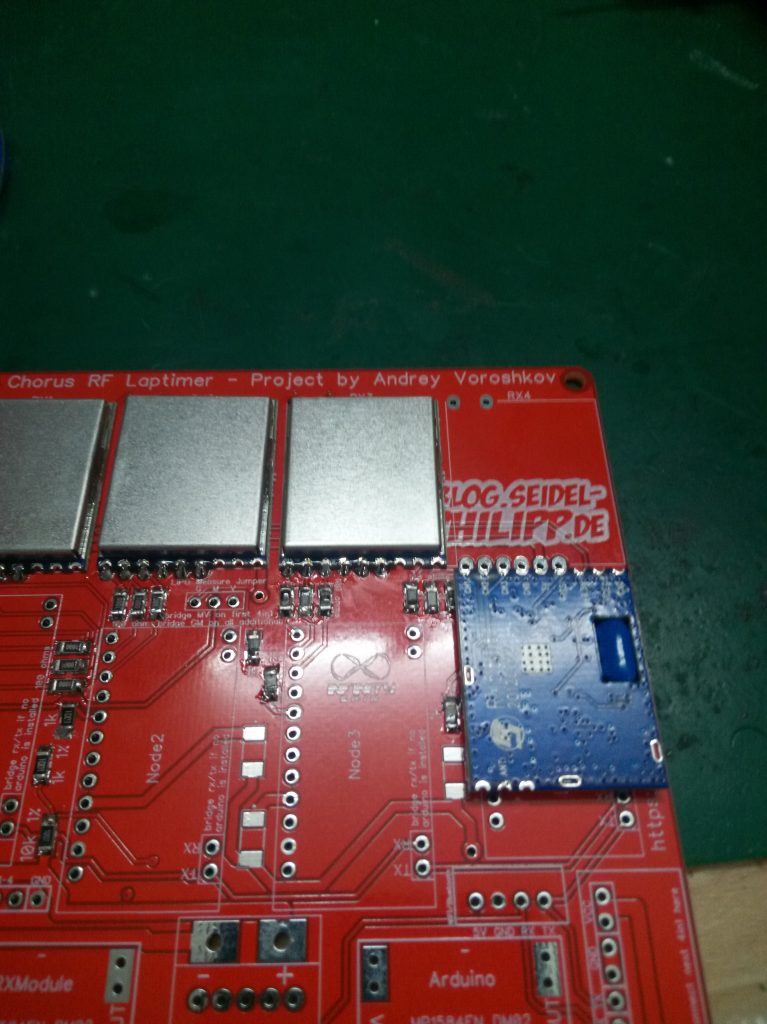
- 4x Boscam 5.8G Wireless FPV Receiver Module
- 4x 5V 16Mhz Arduino Pro Mini Module
- DT-06-Wireless-WiFi (prefered wifi instead bluetooth to get better range)
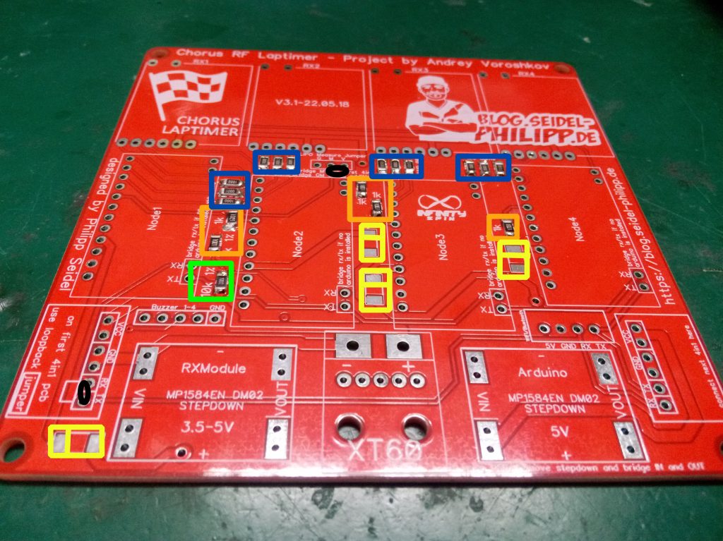
- Resistors, ordered 100 of each once, cause you could always need than anyhow, for the laptimer you need only: 1206 SMD (12 x 100 Ohm, 5x 1kOhm, 1 x 10kOhm)
- set of smd shottky diodes (4 pieces are required)
- some 2.54 headers and sockets
- Optional heatsink set
- Optional buzzer set
- Optional usb breakout set
- Optional XT60 connectors, to be able to power with a lipo.